
As I started preparing everything over the last week to ensure I’d be ready for my last semester in undergrad, I thought about how I’d get work done while I was on campus. The laptop I use daily is a ThinkPad T14s Gen1 that I won in a surplus auction running Fedora Linux, and I realized that some of the classes I’m taking this semester will most likely require using development tools that are only available on Windows. My initial idea for solving this problem was by using KVM as a hypervisor and running Windows 11 in a virtual machine on my laptop, but I realized that this is pretty power intensive and I like being able to last an entire day on a single charge. After some thinking, I remembered that I had previously created a jump box using a Raspberry Pi that could allow me to wake my desktop PC remotely, start a connection over Tailscale, and then I could use RDP to connect to my PC from anywhere. However, due to some constraints in my new home (mainly the lack of ethernet ports, sadly), I realized I needed to create a new solution that could allow me to wake up my computer from anywhere.
I have a small collection of random electronics that I’ve acquired over the last couple of years, and I decided to make it a challenge to not spend any money on this project. While there are plenty of existing solutions on the market for this exact use case, I wanted to build something and thought this would be a fun project to work on. I decided that if possible, I wanted to have this solution be able to wake my PC on the hardware level, instead of using Wake on LAN magic packets like I did previously.
With these constraints in mind, I decided that the best way to go forward was to make a simple circuit connected to a micro controller that would wake the PC using the power button header on my motherboard whenever a wake signal was received. Since I don’t have ethernet available in the room where my computer is located, this solution would need to work over WiFi. The only micro controller that I had on hand that had WiFi built in was an ESP8266 board, which I could program using the Arduino IDE. When thinking about the wiring, I thought a relay would be the easiest way to send a signal to the motherboard to turn on, however I didn’t have any in my bin of random components. What I did find was a 4N35 optocoupler, which I could use to keep my micro controller isolated from my motherboard. With these components, I realized that I had everything I needed to create this system and stash it away inside my computer case.
When considering how I would remotely turn my computer on, I realized that I needed a secure way to communicate with my ESP8266. A method that I’ve used in various other projects is a messaging service using a publisher/subscriber model, or pub/sub for short. Pub/sub is a simple way for one device to publish messages on a channel, and other devices or services can subscribe to the feed to read the messages that other devices have published. In the past I’ve used local services such as ZeroMQ, however I really didn’t want to put my own pub/sub service on the internet as I don’t want to accidentally create a security hole in my home network just to have the convenience of turning my computer on remotely. IoT (or Internet of Things) devices are notorious for having weak security controls and creating vulnerabilities on networks, and I didn’t want to increase my home attack surface. Thankfully, services exist online that are already secure and provide the tools I need to make this project work. Enter Adafruit IO, a free pub/sub service using the MQTT protocol that allows me to securely communicate with my micro controller from any of my devices. The way that Adafruit IO works is by creating a feed for messages, which can then be represented and manipulated using a dashboard. The way that I would implement this safely is by having my ESP8266 request the latest data value from the feed repeatedly, and once a “1” signal is read, the micro controller sends a voltage through the optocoupler to the motherboard that turns the computer on, mimicking the press of a power button. With the initial planning in place, it’s time to build the circuit and write some code to make all of this work.
Electrical Wiring
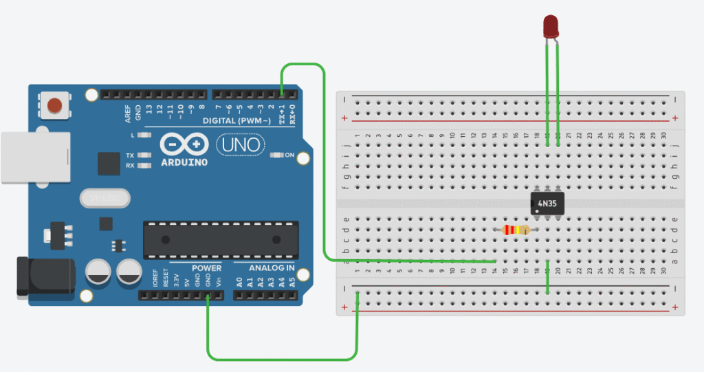
The circuit that I’m using for this project is very simple. The components used for this are some jumper wires, a 220 Ohm resistor, and a 4N35 optocoupler, all connected with a breadboard. In the future I may solder all of this together to make it a bit cleaner, but for now a breadboard works. Below is a diagram of what my circuit looks like in TinkerCAD, which looks a bit cleaner than my circuit in real life. TinkerCAD doesn’t have the ESP8266 as an option, so it’s represented with an Arduino in this diagram. Additionally, the power header on the motherboard is represented by an LED, as the header on each motherboard is slightly different. For my motherboard, the left wire (the collector) is connected to PWRBTN#, and the right wire (the emitter) is connected to GND. On the ESP8266, I have the ground pin connected to the ground rail on the breadboard, and pin D1 connected to the resistor that connects to the anode of the optocoupler.
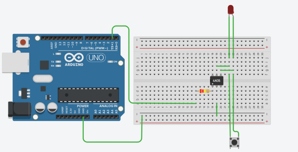
This was the initial wiring that I used, however it become evident pretty quickly that this would make it so I can’t use the power button on the case of my computer…I’d rather not have my computer be inaccessible if my internet goes down, so I made a slight adjustment that allows for the power button to be used as well. This is done by creating two parallel circuits for the output of the optocoupler and the case power button, so if either the button or the optocoupler sends a voltage, it will go through to the motherboard.
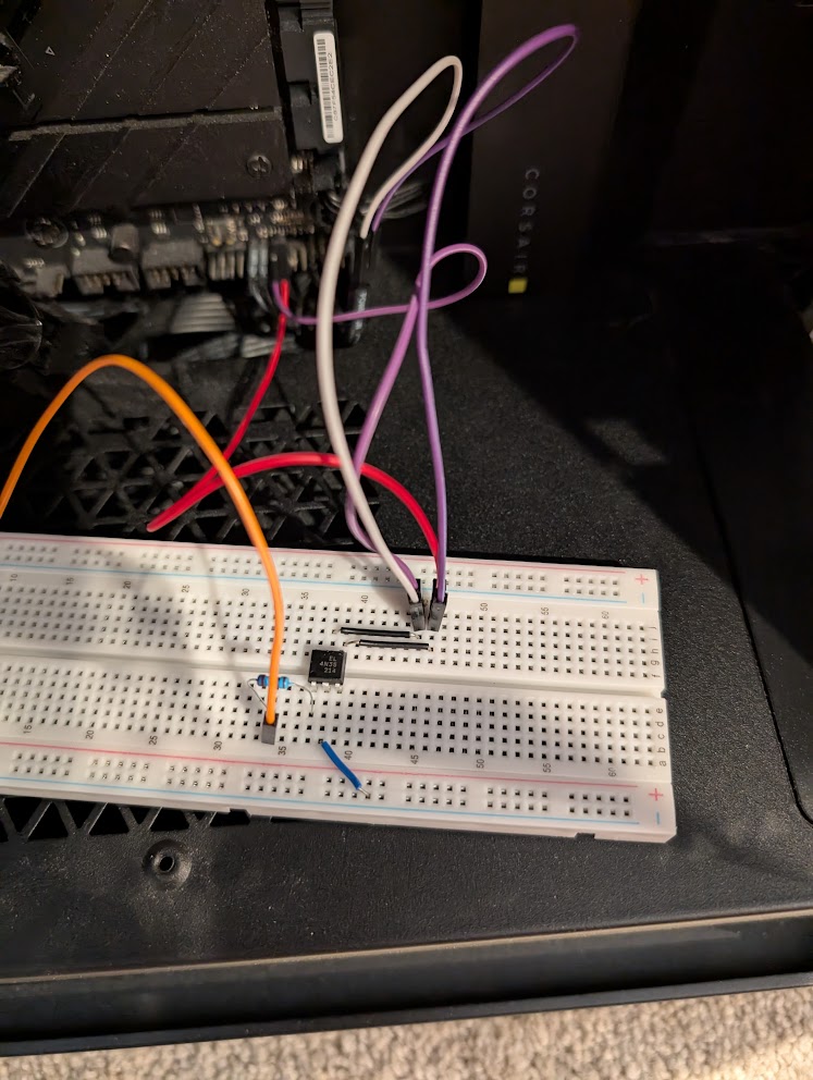
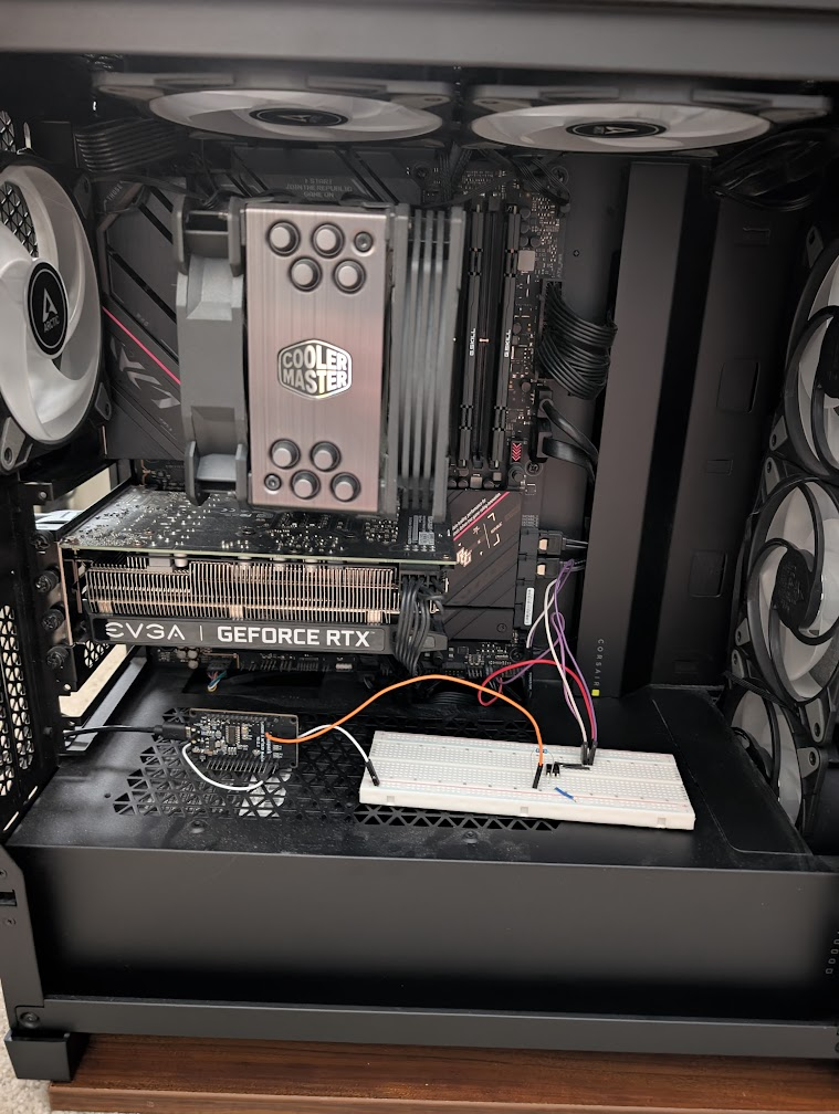
With this planning done, I built the circuit on a breadboard and installed it into my computer. I built the circuit in the open area of the case initially, but I moved it to the basement of the case after finishing the programming. In order for the ESP8266 to be powered, I have a USB cable running through an open PCI slot that is connected to an open USB port on the back of my computer. On this motherboard, the USB ports are powered even when the computer is off, so I don’t need to worry about powering it externally.
Adafruit IO Setup
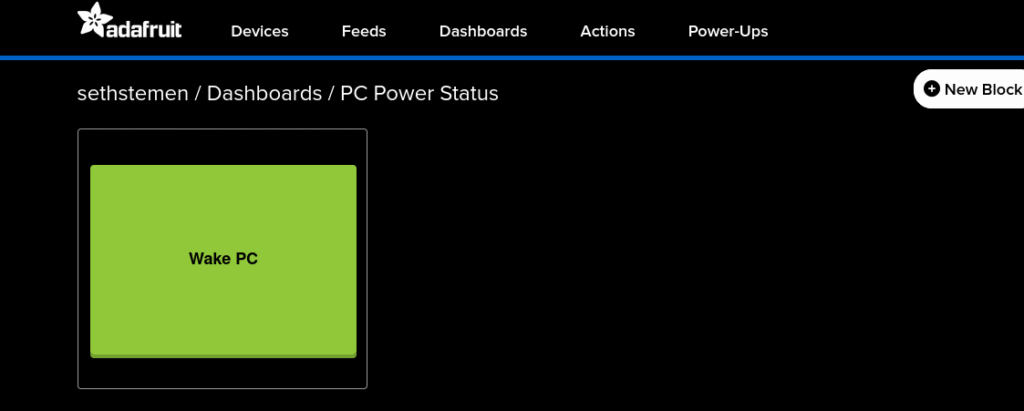
First, I started by creating a new feed called “pc-power-button”. This is the feed that the ESP8266 is going to check repeatedly to see if it should send a signal to the motherboard. The only other setup that needs to be done on Adafruit IO is setting up a dashboard to provide an easy way for me to turn the computer on from anywhere. This is as simple as going to the “Dashboard” tab and creating a new dashboard. I decided to call mine “PC Power Status”. with it’s key being set to the “pc-power-status” feed that I previously created. I added a new button to the dashboard, and set it to send a “1” signal on the pc-power-status feed when pressed. This is the only configuration that needs to be done on Adafruit IO to make this project functional.
The Programming
I wrote this code in the Arduino IDE thanks to some support packets that were created for the ESP8266 board, and I’ve published the entirety of this code on GitHub if anyone decides that they want to repeat this project. This code does require two libraries from Adafruit to support the MQTT connection, in addition to a library to establish a WiFi connection on the ESP8266. The top portion of the code serves as place to fill in required variables, such as WiFi network information and login information for Adafruit IO.
// GPIO5 = D1
#define RELAY_PIN 5

// Replace with your WiFi network credentials
#define WLAN_SSID       "SSID"
#define WLAN_PASS       "PASSWORD"

// Replace with your Adafruit IO credentials
#define AIO_SERVER      "io.adafruit.com"
#define AIO_SERVERPORT  1883
#define AIO_USERNAME    "USERNAME"
#define AIO_KEY         "API_KEY"

// Adafruit IO pub/sub topic
#define POWER_FEED      "pc-power-button"

WiFiClient client;
Adafruit_MQTT_Client mqtt(&client, AIO_SERVER, AIO_SERVERPORT, AIO_USERNAME, AIO_KEY);
Adafruit_MQTT_Subscribe powerSwitch = Adafruit_MQTT_Subscribe(&mqtt, AIO_USERNAME "/feeds/" POWER_FEED);With the initial variables created, the setup function establishes the WiFi connection and sets D1 on the ESP8266 to an output, followed by subscribing to the Adafruit IO topic.
void setup() {
  Serial.begin(115200);
  delay(10);

  Serial.println(F("Remote PC Power Controller Booting..."));

  pinMode(RELAY_PIN, OUTPUT);
  digitalWrite(RELAY_PIN, LOW);

  Serial.print(F("Connecting to WiFi: "));
  Serial.println(WLAN_SSID);

  WiFi.begin(WLAN_SSID, WLAN_PASS);
  while (WiFi.status() != WL_CONNECTED) {
    delay(500);
    Serial.print(F("."));
  }
  Serial.println();
  Serial.println(F("WiFi connected"));
  Serial.print(F("IP address: "));
  Serial.println(WiFi.localIP());

  // Setup the Adafruit IO subscription
  mqtt.subscribe(&powerSwitch);
}With the WiFi connected and topic subscription active, all that remains is to repeatedly poll the Adafruit IO feed until a message is received, and handle each received message accordingly. I’m only concerned with messages that match “1”, as this is the signal that the Adafruit dashboard button will provide when it is pressed – indicating that the PC should be woken up.
void loop() {
  // Reconnect automatically if the connection is lost
  MQTT_connect();

  Adafruit_MQTT_Subscribe *subscription;
  while ((subscription = mqtt.readSubscription(5000))) {
    if (subscription == &powerSwitch) {
      Serial.print(F("Received message on feed '"));
      Serial.print(POWER_FEED);
      Serial.print(F("': "));
      // Cast byte array to char array
      Serial.println((char *)powerSwitch.lastread);

      if (strcmp((char *)powerSwitch.lastread, "1") == 0) {
        pressPowerButton();
      }
    }
  }

  delay(100);
}

void pressPowerButton() {
  Serial.println(F("Sending power button press"));
  digitalWrite(RELAY_PIN, HIGH);
  delay(200);
  digitalWrite(RELAY_PIN, LOW);
}Additionally, I have built in some redundancy should the connection to Adafruit IO be lost. Since this device is going to remain in my computer long term and I’m not going to be monitoring the serial output after writing and debugging the code, there is a mechanism built in to have the ESP8266 reset itself if there are repeated failures to reach Adafruit IO.
void MQTT_connect() {
  if (mqtt.connected()) {
    return;
  }

  Serial.print(F("Connecting to MQTT"));

  int8_t ret;
  uint8_t retries = 3;
  while ((ret = mqtt.connect()) != 0) {
    Serial.println(mqtt.connectErrorString(ret));
    Serial.println(F("Retrying MQTT connection in 5 seconds"));
    mqtt.disconnect();
    delay(5000);
    retries--;
    if (retries == 0) {
      Serial.println(F("Failed to connect to MQTT after multiple retries. Resetting"));
      ESP.restart();
    }
  }
  Serial.println(F("MQTT Connected!"));
}Initial Testing
After some troubleshooting with wiring and debugging the ESP8266 code, pressing the “Wake PC” button on the dashboard will wake up the computer even if it is completely turned off – success! Pressing the power button the case also works exactly the same as before, so this project is already in a great spot. To make my computer a bit cleaner, I stashed away the breadboard and ESP8266 in the basement of my case. With the circuit out of view, it’s really difficult to tell that anything has changed when looking through the side panel, so this turned out really well.
While this project is functional in its current state, I wanted to take it a little bit further. When looking through the blocks on Adafruit IO, I saw that there is an indicator option to show if a device is online. I realized that it may be nice to remotely see if the computer is still on, so I decided to go a bit further and get the indicator light working.
Creating the Indicator
After playing around with Adafruit IO for a while, I realized that my solution for this was going to be a bit sub-optimal, but I’m playing within the rules of the free subscription. My idea for creating the status indicator is to have my PC send signals to another feed, like a heartbeat, so the indicator will turn red if any heartbeats have been missed. The issue I ran into immediately is that Adafruit IO doesn’t have some features of MQTT that I was banking on, such as Last Will and Testament – a feature that will send a message once the connection between the device and MQTT broker has timed out. Without this in place, I realized that I would have to create my own version of LWT to be used on this site.
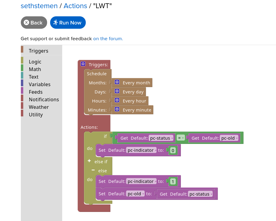
Adafruit IO has support for creating small scripts that are triggered based on a variety of conditions, called “Actions”. I figured this would be the easiest way to create my own implementation of the Last Will and Testament feature. Adafruit Actions are created in block based code, and it doesn’t seem that there is any retention of variables between triggered runs of the script, so I had to get a bit creative. My idea for implementing the heartbeat signal was to use a rolling count, where every 30 seconds my PC would send a number between 1 and 5 in incremental order to a feed called “pc-status”. I created another feed that stores the last rolling count value seen by the action code, called “pc-old”. Every minute, the action will check the current rolling code against the last rolling code that was seen, and if these two values match, then the computer must be offline, otherwise it must be online. The determined status of the computer is then written to another feed called “pc-indicator”, which will be referenced on the dashboard I created earlier. I had to use this rolling count based method as Adafruit Actions does not have any sort of time checking that can be used to simply say “if a signal hasn’t been received in 60 seconds, set the indicator status to off”. This algorithm can be seen represented in block form below.
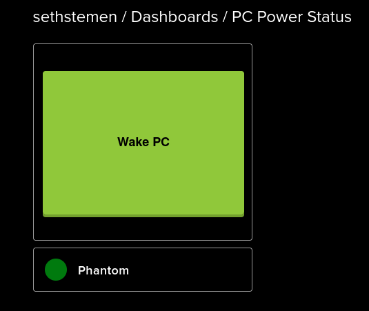
In order to get this working on the dashboard, I created a new indicator block and tied it to “pc-indicator”, and set it to show a green light if pc-indicator = 1, otherwise show a red light. This is all of the configuration needed on Adafruit IO, and it’s time to create the code on my desktop to send signals to pc-status.
Creating the Heartbeat
I decided to write this code in Python as it is helpful for quick and dirty scripting, and this code doesn’t need to be very robust at all. The way this code will work is by establishing a connection to Adafruit IO, send a rolling count to the pc-status feed every 30 seconds, and reestablish a connection in the event of a disconnect caused by the computer going to sleep. This code will be included in the same as the ESP8266 code in case you wanted to recreate this project, just keep in mind it’s most likely not the cleanest solution available.
This script does require the Adafruit_IO library, which can be installed using pip install Adafruit-IO. The top portion of the code is very similar to the ESP8266 code, which calls for information to connect to Adafruit IO in addition to defining the interval for the heartbeat.
from Adafruit_IO import MQTTClient
import time
import sys

AIO_USERNAME = "USERNAME"
AIO_KEY = "API KEY"
AIO_FEED = "pc-status"

HEARTBEAT_MESSAGE = 1
HEARTBEAT_INTERVAL = 30The main function repeatedly sends an incrementing rolling count to the pc-status feed on Adafruit IO, and attempts to reconnect in the event that the connection is lost. The reconnection logic is important, as once the computer goes to sleep, it will sever the connection between Adafruit IO and the computer.
if __name__ == "__main__":
    client = MQTTClient(AIO_USERNAME, AIO_KEY)
    client.on_connect = on_connect
    client.on_disconnect = on_disconnect

    try:
        print(f"Connecting to Adafruit IO")
        client.connect()
    except Exception as e:
        print(f"Could not connect to MQTT broker: {e}")
        sys.exit()

    client.loop_background()

    try:
        while True:
            if not client.is_connected():
                print("Connection lost. Attempting to reconnect")
                try:
                    client.connect()
                    print("Reconnected successfully")
                except Exception as e:
                    print(f"Failed to reconnect: {e}")
                    print("Retrying in 15 seconds")
                    time.sleep(15)

                    continue

            if(HEARTBEAT_MESSAGE > 4): HEARTBEAT_MESSAGE = 1
            else: HEARTBEAT_MESSAGE = HEARTBEAT_MESSAGE + 1

            print(f"Sending heartbeat '{HEARTBEAT_MESSAGE}' to feed '{AIO_FEED}'")
            client.publish(AIO_FEED, HEARTBEAT_MESSAGE)
            time.sleep(HEARTBEAT_INTERVAL)

    except KeyboardInterrupt:
        print("\nStopping")
    finally:
        client.publish(AIO_FEED, "0")
        time.sleep(1)
        client.disconnect()
print("Disconnected")When testing this code, I found that it worked in lighting up the indicator light on the dashboard – another success! When the computer goes offline, it takes around 1-2 minutes for the indicator light to switch to red, mainly due to limitations with Adafruit’s action system (which is totally understandable for a free service, I believe you could schedule actions more frequently on a paid plan). All that remains is to schedule the script to run in Task Scheduler when the computer turns on, and the indicator will show if the computer is online or offline from anywhere in the world.
Ultimately, this project turned out extremely well and will be very helpful for me as I return to school for my final semester of undergrad. This was a fun project and I will definitely be returning to the world of micro controllers in the future.